Contents
Preface
I came across this challenge by Jane Street when my PI sent me a link to it and suggested that it is ‘an interesting area to hack on’, because it might closely resemble my own research work. I have spent over a week working on it nearly full-time. I spent the previous 2 weeks learning OCaml and getting bamboozled by memoization and functors, so this was a refreshing filler before I moved on to Monads and GADTs.
AI Usage Disclosure
I have used Claude Opus 5 along with Claude Code extensively throughout this puzzle. At no point did I ask AI to come up with ideas or give it the GDS file, the Verilog netlist or the outputs and ask it to give me the answer. Here is a clear breakdown of what I did use AI for:
Where I used AI
- To write scripts. This entire project uses Python as the primary scripting language and also as the language for tight REPLs to debug and analyze the contents visually. More than 90% of the Python code in the repository is AI-generated.
- To build an understanding of the various components of the problem. My chat transcript is full of questions like “What is a dfrtp?” and “What does
alwaysmean in Verilog code?”. - To verify the correctness of my understanding and validate my approach.
- To understand how to use tools like KLayout.
Prologue
The problem gives us a GDS file and asks us to figure out the circuit’s true purpose. It also gives us a warmup puzzle, where we are given the various steps an engineer goes through to arrive at such a GDS file, from human-readable Verilog source code to the GDS file. The problem is intentionally vague about what is the deliverable, but this is something I came to appreciate only after I managed to crack it open. Beyond the warmup puzzle, the actual puzzle’s GDS, a README.md file, an image of the circuit, an example input and a few tips on the tools one can use, the GitHub repository isn’t very helpful either.
My plan was to use the warmup puzzle as an anchor to write a pipeline to which I could simply feed the main puzzle and get my ‘answer’. The plan is to spend most of my time on the warmup and sharpen the tools in the pipeline, make them so general that they can be run on any GDS file with a single command and the right arguments to get the input sequence required to ‘solve’ the problem. I believe I have mostly succeeded in doing so.
Everything I wrote to solve the puzzle can be found in this repository forked from the puzzle repository.
I used Python 3.14.7 in a venv (dependencies present in requirements.txt). I am using VSCodium as my code editor, with the following extensions installed:
- Python Language pack by Microsoft
- Ruff by Astral Software
- Rainbow CSV by mechatroner
- Verilog-HDL/SystemVerilog by Masahiro Hiramori
I used KLayout 0.30.12-1 to view the GDS file.
Chapter 1: High Level Approach
- Starting with a GDS file, we survey it to ensure that it is well-formed and that all the cells present in the GDS can be identified.
- Convert the GDS into a netlist, similar to
02_netlist_with_power_railsin the warmup. - Run sanity checks on the extracted netlist to ensure that basic conditions such as a consistent clock input to all cells, no hanging wires etc are satisfied.
- Clean the netlist, giving us something similar to
01_netlist.v, which removes some of the noise by removing the power/ground pins (only input pins affecting logic are preserved) and adds information by inferring the ‘direction’ of the pins, i.e. identifying which are the input and output ports. - Use SAT solving techniques to encode the constraints of the netlist and solve for an input sequence which results in a desired, specified output.
- Cross-verify the solution by simulating the circuit with the SAT inputs.
- This is where the problem stops being mechanical and requires some insights based on observation of the outputs. Play around with some of the SAT inputs and try to notice patterns in the inputs and the resulting output.
- This is specific to this problem; watch the output and try to decode what it is trying to tell us.
In the next chapter, I will explain my reconnaissance of the warmup problem. The chapters following that will be detailed explanation of the steps mentioned above.
Chapter 2: Reconnaissance and the Warmup Problem
Forward Pass
The warmup problem gives you a Verilog source file which contains the following modules:
- A
shift_registerwhich maintains the state as a 1 byte register. If enabled, it takes a 1 bit input, shifts the existing register and writes the input to the LSB. This is the only piece of sequential logic in this circuit. - A simple
adder8which takes two 8 bit inputs and writes the sum into a 9 bit output. This is purely combinational. - A
comparator496which takes a 9 bit input and has a 1 bit output which goes high if the the input bits in decimal match 496. - The overall chip combines these into a top-level module called
adder_demowhich when enabled after a reset, takes 2 input bitsAandB. It has an internal state of two 8 bit registers which start with 0 and on each clock cycle, shift the registers, append the inputsAandBto each one and compare the addition of these two registers to 496, which on succeeding, sets theSbit to high.
The source file is the easiest one to read. It is then ‘synthesized’ which is like a compilation step that converts this circuit into a ‘netlist’ which uses standard cells from the sky130 library to replicate the functionality. This step is irreversible. This file is genuinely hard to read; for the combinational logic, it often uses cells which takes several inputs and return some logical formulae on these inputs, which often feels random, such as ((A1 & B1) | !C). The library provides us with a large number of cells in the library which can be used to implement complicated combnatorial operations efficiently.
The second type of cell it contains are dfrtp cells, which are used to implement sequential logic. These cells are the type which have ‘memory’ and depend on the clock to modify their state.
Understanding what exactly is going on over here is a steep learning curve for me and I used AI extensively to understand what each and every piece meant.
Here is the fully annotated artifact generated by Claude I put together to break down what each line does. It builds up an understanding of HDL through 9 questions and a line-by-line walkthrough of the source Verilog code.
The next step is a minor addition over the netlist, it is the same thing with power rails. Very important from a physical design POV but unnecessary when the problem is viewed from the lens of logic.
The step after that converts the netlist, an algebraic description of the circuit into a geometric description, a file which tells where on the chip each cell is placed and how it is wired. It is exactly this geometry which is shown as a GDS file.
Reconnaissance
Honestly, there isn’t much reconnaissance over here. I tried to do CTF Forensics style recon and nothing turned up. I did the standard stuff:
Using file, exiftool, hexdump etc on the layout.png, the puzzle.gds etc but nothing returned anything. Honestly, I was hoping to get a cheap Easter Egg out of this, but I had clearly underestimated JS because these files were totally innocuous.
Approaching…
Once I understood the structure of the problem, I had 3 approaches in mind, in increasing order of difficulty:
- Treating the problem as a Logic problem. Here, I convert this circuit into a Boolean formula which try to solve for the
Spin going high. The obvious challenge here is that standard Boolean or first-order logic, the logics I am familiar with don’t handle ‘memory’ but a little bit of poking around made this trivial. - Treating the problem as a Machine Learning problem. I was inspired to take this approach based on what I saw in the warmup problem. The idea is to collect ‘data’ by throwing a large number of inputs at the circuit and trying to ‘learn’ the internal states and finally the logic behind the success pin. I thought that this could be an approach since the number of feature variables initially seemed small and I believed one could use techniques like symbolic ML to learn the expression trees which generate the circuit outputs. Maybe even using some visualization, by plotting inputs vs outputs and seeing if any obvious patterns emerge.
- Treating the problem as a Hardware Design problem. There are a few patterns I noticed in the warmup, such as the cells in the netlist which handled equality comparison. They all take bits of the sum as input and compare some logical combination of them with a constant. This clearly points to equality checks and in case I am able to identify enough groups of such cells, I can intuitively draw out what the circuit does. In retrospect, this would’ve been insanely challenging since the reverse direction doesn’t retain any of the helpful register names like
sum, so I’m just thankful it didn’t come to this.
Luckily for me, I was able to arrive at the answer with my first approach. Had time permitted, I would’ve loved to use the third approach as an exercise, but today, that’s a challenge for another day.
All of the following steps now work parallelly on the warmup as well as the actual puzzle file unless specifically mentioned otherwise.
Chapter 3: Surveying the GDS File
Our best friend over here is the klayout Python library and the module celllib, a user-written library which handles identification of cells. We start by running the script survey.py on the GDS file without any other arguments. Inspect for any cells which we cannot identify.
In case we want to inspect a cell in greater detail since it cannot be identified, one can use the --cell cmdline argument to do so. This is actually a problem I faced when I tackled the main problem after the warmup, since it contains new cells which weren’t present in the warmup and my library had hardcoded the cells present in my warmup.
Once this passes, run it again with --check-lib, inspired by the previous mistake to check that our own cell library is complete.
Chapter 4: Extracting the netlist from the GDS File
This is the magical step which converts the geometry problem into an algebra problem. It is exactly the reverse of the step which took us from 02_netlist_with_power_rails.v to 04_final.gds.
Honestly, I still don’t fully understand how it works. All I know is that the good folks building klayout have provided me with a magic class named LayoutToNetlist which does exactly what we want. As far as our problem is concerned, this module is nothing more than a wrapper over that, which takes a GDS file as an input, the name of our resulting netlist and writes that netlist to the disk.
Chapter 5: Sanity Checks
This is the step which has helped to catch many of the bugs in my code as well as ensured that our work is verifiably correct at some level. These checks are all present in netlist.py. This file takes as input a netlist which we generated after extraction and allows you to run the following transformations:
- Converting the netlist graph into a JSON
- Showing you the drivers of each wire
- Showing you the inferred ports and their respective fanouts
- Showing you the cell library we have
- Giving you the driver of a net (which output port) and the cells a certain net drives (and which input port)
- Analyzing the deep dependencies and dependants of a net, i.e. the forward and backward cone
- A free sanity check on each net to ensure that it has a single driver and that there are no hanging wires, i.e. wires which are driven neither by an input port of the circuit nor by an internal cell
- A clock report to ensure that there is a single synchronised clock for each cell in the circuit
It is important to run these checks on the recovered netlist to ensure that there is no funny business and the extraction was correct. It can save us (or in the case of the main puzzle, give us T-T) sleepless nights in debugging difficult bugs. Moreover, it is also an assertion to the correctness of the previous and following steps.
Chapter 6: Cleaning the netlist
In this step, we do 2 important things:
- We remove the power lines because they are a physical artifact and have nothing to do with the actual logic of the puzzle.
- We use graph algorithms to figure out directionality and the flow of information.
To elaborate on the second point, by the definition of each cell extracted from the cell library, we know what are the input and the output pins. The netlist extracted by extract.py does not contain information about direction, i.e. which is the input and which is the output, because it just sees wires. Just by seeing a wire, you can’t determine the direction of the current and here, the direction of the input and output, so it needs to be inferred by finding out which ports are present only as inputs and never as outputs and doing a dictionary-lookup from there till we reach ports which are only driven and never drive anything.
This is the second instance where we use such graph search algorithms. The previous instance was in netlist.py to find the cones of a net, which uses DFS.
Running this step now leaves us with a clean netlist which is easier to analyze.
Chapter 7: Solving the circuit
This is, without doubt, the most important step of the puzzle. In this step, we use an out-of-the-box SAT solver (z3) to solve an equivalent problem to the circuit.
It’s important to understand why SAT solving is the right approach here:
- We are dealing with a circuit which maintains state and has a clock. Inputs are read once per clock cycle and they pass information through the circuit, so there is a natural temporal direction to the problem
- We do not know before-hand how many clock cycles we need to tune whichever output
- Thus, a naive approach would be to just do a grid-search over the input space, which is all possible input sequences of length 1, all possible input sequences of length 2, all possible input sequences of length 3 and so on ad infinitum till we find an input sequence which turns a required pin or set of pins high. Clearly, this is exponential in the length of the first winner input sequence, in the best, worst as well as average case. Impractical to iterate this on regular hardware.
- But, if we somehow manage to unroll the time axis ‘orthogonal’ to the input state and perform a SAT check to see if we can find any input array which turns the success pin in the final, unrolled iteration high, we have found a valid input sequence. This is not a novel idea I can take credit for, it is a well known technique inspired by Loop Unrolling for Bounded Model Checking in formal methods
- The worst case time complexity is still exponential here, but since modern SAT solvers are so good, they manage to do this in a matter of mere seconds.
This is exactly what solve.py does. An important variable here is the number of cycles for which we unroll and this is something one just has to play around with. Or one could start with the default, 16 and double it every time we find something UNSAT for the current unrolling length till we find a SAT input sequence.
solve.py is the largest file in our toolset and also the one with the most powerful features. It tries to squeeze as much out of z3 as I can to use SAT solving to tackle our problem, since this is something which falls right into my ballpark. It has a ton of features, such as allowing one to set the goal pin, holding a certain port (such as the enable pin) to a value, resetting for a few cycles to get the state back to neutral, verifying with a simulator, minimizing the input sequence to discard unnecessary bits and also finding multiple SAT solutions.
Most of these features are just built on top of what z3 already provides and the main challenge here is to convert our circuit with its fancy gates and memory cells to a SAT problem which z3 understands.
Understanding how unrolling works for circuits is something which can be helped a lot by a visual explanation. Here is a Claude-generated artifact which explains this beautifully.
Chapter 8: Cross-verification
The previous step gives us the inputs but it works completely on the unrolled circuit. We now need to simulate a clock and send these inputs one-by-one each clock cycle to our circuit and verify whether it actually works. The script which helps us do this is sim.py.
This script takes a netlist as an input and converts each physical/logical cell into a Python object which takes equivalent inputs, gives equivalent outputs and performs an equivalent logical operation. In each step, it simulates one clock cycle.
To run this script, we must give it the inputs we want to drive. It has several features which allow us to watch the internal state (registers) and hold inputs (useful for enabling, resetting). Note that this script is stateless between runs, so it does not preserve state once it has finished running.
Chapter 9: Sim Analysis
Now, this is the step where the approaches diverge for the warmup puzzle and the main puzzle. Let me address the warmup puzzle in this chapter and the main puzzle in the next one.
To start off, the first observation is that when we --minimize our SAT inputs, I noticed the inputs turn into - or don’t care whenever en is turned low. It’s clear that this is by design and en should not be considered like an input which drives the internal logic, but rather something which turns it on, something that the source Verilog immediately confirms.
So I go back to solve.py and rerun the SAT solver by holding it high, using --hold en=1. This considerably minimizes the length of input sequence which we require to get S high. I rerun it again with --all-solutions to an absurdly high number to get all possible solution and voila, we arrive at all possible input sequences A and B which turn S high. Notice that they all turn S high at the the first clock cycle 8 or 9.
On a side note, how does this work? It works by first finding one SAT input. Then we rerun the SAT solver with the additional constraint that our input must not EXACTLY match the previous SAT input. Then again with another constraint to not match either of the first two. We keep doing this till we reach UNSAT, which means we have provably found all possible solutions for this unrolling length
It is helpful to dump all the runs along with their input and output sequences into a CSV or similar format to allow visual inspection. It becomes clear on doing so that A and B appear to sum upto 496 in all SAT inputs and thus we have figured out what the circuit does. sweep.py is a script which helps us automate these runs, but, full disclosure, I have only run this for the main puzzle and not for the warmup puzzle.
Chapter 10: Decoding the outputs
Coming back to the main puzzle, here is the sequence of steps I arrived at (although the real problem-solving involved a lot more trial and error than what I mention over here) to find the desired string:
- Same as the warmup puzzle, the
enableinput pin over here also seems to driving a LARGE number of cells at once (confirmed by runningnetlist.pywith--affects enable), so let’s just pin it down to 1 (along withrst_nof course, since the puzzle explicitly mentions we must reset before a fresh run and we need this circuit follows a low reset pattern) and run the SAT solver. - The SAT solver does take nearly a minute to find a SAT output, starting from 12 cycles upto 1024 cycles (arbitrary choice).
- Alright, it seems to turn
successhigh on a very specific input. I now try running the same SAT problem with the max number of cycles 121 and it comes out UNSAT! That proves that we need at least 122 cycles. I choose 121 because that was the clock cycle whensuccesswas low for the last time. - Now with 122 cycles I try running
solveagain but trying to find multiple solutions. But it returns saying there’s only a single solution! This proves one thing: this circuit is like a lock which is looking for a key which makessuccessgo high and only that unique key works. - Alright, let’s see if what happens if we increase the number of cycles. Increasing it to ANY number now, even 150 with holding
rst_n=1andenable=1gives only 1 solution! This is huge! It means that only the first 121 inputs matter and once you get that right, nothing else matters, you can enter whatever you want and success stays high forever. But note that our SAT solver only cares aboutsuccess, as far as it is concerned, the outputO[7:0]pins don’t even exist. - Great, so now we go with our winning input sequence and dump it into
sim.pyso that we can observe the output as well. Since our SAT solver has officially confirmed that nothing after 121 matters, we can do whatever we like. And voila! The output stays 0 till success goes high, turns on momentarily and goes back to 0 after exactly 15 cycles. Each time. - Let’s see if there’s something we can tease out of the output by just feeding it the right key followed by arbitrarily large inputs, upto 200 length even? We generate several such inputs and run them using
sweep.pyto generate CSV files which give us the output for 24 such runs. Observation: The output is the same every time! - So, the constant output is 8 bits or 1 byte long. What if we just see
O[7:0]as a byte and convert it to its ASCII encoding, since that is what can give us something close to a string? Here’s a simple one-liner script which takes the (converted) decimal representation of the outputs and feeds it to an ASCII converter:outs = [40,42,32,84,87,79,32,83,84,65,82,83,32,42,41];print(''.join(list(map(chr, outs)))) (* TWO STARS *)
Challenges and Gaps
Needless to say, each step over here came with its own challenge. Since I never wrote a single line of code myself, coding complexity was never a challenge, it was always understanding, coming up with the right approach and verification.
Challenges
- Understanding the language of HW Design. I realized that a lot of unknown terms I was flabbergasted by on Day 1 are actually concepts I am quite familiar with. Climbing the wall of HW tooling was my primary challenge in the initial days.
- Working with KLayout proved to be a major hurdle. I was quite unfamiliar with the UI/UX of KLayout and doing even basic stuff like moving around or seeing cells required a quick Google search. Worst of all, I didn’t even know if something was actually not working or if I was just doing it wrong, because there were many such encounters.
- Again, from KLayout, I initially started out by using KLayout’s own script editor and runner. The logic was simple, I did not want to install a Pyhton library which just interfaces with KLayout, I’d rather use their own API to manipulate the GDS and extract the netlist than an SDK. But I kept running into an annoying bug where I could not run any script other than the first one I created on starting up. It seems like a unique bug because I couldn’t find any mentions of it online. Eventually, after running into several bugs, I realized that VSCodium is a much more convenient text editor and I should just use the KLayout SDK and gave up altogether. I think this could be because KLayout doesn’t have first-class support for my OS. I use Arch BTW.
- This one is completely irrelevant to the challenge but it made one of my afternoons significantly more eventful. This is my favourite one because it is a bug of an intensity which is absolutely unimaginable. It comes again, from… KLayout 😢
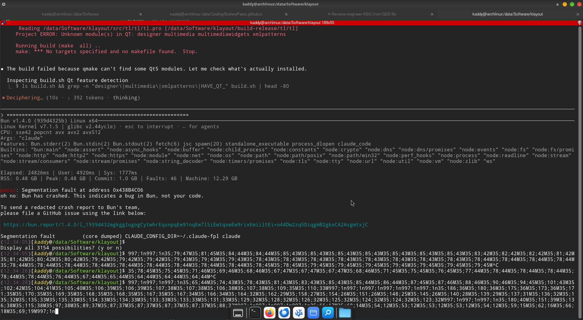 To explain what is going on over here: I initially tried compiling
 klayoutfrom source since I couldn’t find native builds for Arch on their GitHub and I kept running into a compilation error, so I decided to point Claude at it so that it could figure out the whole compilation pipeline. So I ran./build.shinside Claude by starting it with!. But, this just ended up crashing Claude Code itself with an uglybunerror. And I think the TUI did not exit gracefully, because it seemed to ruin my terminal inputs irreversibly.
But this wasn’t the worst part, the worst part is what came after this when I restarted my machine to take things back to normal and my bootloader complained that it couldn’t find my kernel. Okay, that happens sometimes, let me just reboot again. And again. And again. Till I realized that something was seriously wrong and I spun up a GRUB terminal and checked my boot partition. And lo and behold, myvmlinuz-linuximage is gone! No wonder I couldn’t boot up, I had nothing to boot from. After booting up from a flash drive and reinstalling Linux, I learnt a valuable lesson: Always keep a bootable drive with your distro on you at all times. I can’t prove that theklayoutcrash is the one which wiped off my OS, but it seems connected and I’m afraid of retrying it to confirm. Frankly, I don’t even know how this could even work, how could a build script which is not even run withsudowipe out my OS?! Nonetheless, diagnosing this could be my next interesting project :) - The last challenge is a serious one: Verifying whether my cell library is correct. The cell library is the source of truth in my code from which the simulation, the SAT solver are built. The logic built into the cell library tells how to write each cell as a logical formula in Python. So, if my cell library says that sky130_fd_sc_ls__a21oi is a cell with input pins
A1,A2andB, output pinY = !((A1 && A2) || B), that better be the case, otherwise every instance of this cell in our circuit is understood and simulated incorrectly. It can be disastrous and leave us with nearly impossible to find bugs and this is what I did deal with when I moved on the real puzzle from the warmup and was hit with a bunch of unknown cells which were not part of my cell library. This problem arises because the cell library has been generated by AI and hardcoded as a Python data structure inside a script/module. This is not the correct approach, we must either: write a deterministic script which can guarantee that it produces the correct description of a cell from its name. Since there is no direct sky130 API nor do the unofficial docs provide an easy way to scrape the logic from a cell, we must refer to the library and write our own parser to do it. This is what thepdkdirectory contains, it contains both the Verilog and the Liberty docs for each cell. This might seem like an overkill, but given how critical this is, it is essential that we double-check our cell library, which is exactlyextract_cells.pyandcrosscheck.pydo. The documentation for sky130 brings it’s own challenges and it is difficult to dig as deep manually as one can go with AI here.
Gaps
- As it must be clear by now, I am very paranoid about the completeness and soundness of AI generated code and while I’ve put several reinforcing checks, a big gap is in
sim.py. Our entire solution rests onsim.pytruly simulating the real behaviour of the circuit on any possible input. What can go wrong? Maybe Claude hallucinated and we are just generating random output which is somehow, luckily consistent and exactly what we want on each run (the probability of this is non-zero). Maybe we are off by one in clock cycles. Maybe the code has a terrible bug which when given a correctly formed input can execute a copy.fail type privilege escalation attack. Okay, those are unlikely, but it’s possible that there is just some simple logical bug insim.pywhich leads to inconsistent outputs. It’s possible because there are several layers of abstraction here. We can never be sure unless it is formally verified. - This is a literal gap in the circuit, a literal gap in the wires. A missing connection perhaps. This is something which my scripts complain about on every step after extraction, especially
netlist.pywhose job it is to catch such nasty bugs. Okay, so when you extract the netlist from the GDS, you see thatnet n1447is undriven. It is feeding cells as it should, in fact, if you find its forward cone, you can see that it even drives 2 output bits. But there is nothing drivingn1447. It doesn’t depend on any of the inputs. Now, I initially thought that this would lead to an Easter Egg, so I tried to play around with it. I even added functionality in my simulator to simulate hanging wires such as this. But after trial-and-error, I can’t find anything. I thought about emailing JS about this, but since I still believe it is the trail to an Easter Egg, I’ll refrain from doing so. I do not know how to spot this on the circuit board, but I have a feeling following this wire on the actual geometry leads to somewhere, where that is remains a gap in my understanding. - JS hints that the clues to solve the circuit are right there on the die, in the placement on the cells. This is the thread I did not feel comfortable pulling at. I had committed to my SAT Solver approach and working with the chip geometry proved out to be more challenging and I didn’t even have the time. Using tools like KLayout more effectively to utilize this hint remains a gap.
Easter Eggs
Now, I did not start hunting for Easter Eggs till the last day, 4th September. Actually I am not even sure whether most of these (except one obvious one) are even Easter Eggs. However, my hunt for Easter Eggs is actually what truly made me see what the circuit actually was, beyond just SAT solving, as an actual puzzle. Here’s the grand reveal:
The circuit is a Star Battle Puzzle. The inputs are not on a line, but rather, the 121 length input string populates row-wise a 11x11 board which solves the Star Battle Puzzle.
How I figured this out
I was hunting for Easter Eggs CTF style in all the files and the most suspicious file was example_inputs.vcd since this file seemed to serve no purpose at all in the puzzle. Opening it in a waveform viewer was also useless, until I noticed that these inputs also gave a non-zero output on the 122nd cycle.
On trying out random 150 length strings, I realized that this was the same output which was emmitted on every single string I tried and using the same ASCII decoding scheme as the answer, it reads TRY AGAIN, a cheeky response to these failed attempts.
Now, I was curious as to what all can this circuit even emit. To do this, I wrote sim_special.py. This is written mostly on top of solve.py and even it solves a very specific SAT problem. While the main puzzle solves for the success, here, we solve for the output, to be specific, we solve for: Can we find any input sequence which gives an output other than the ones we’ve already seen, i.e. the answer and the ‘TRY AGAIN’?
So, in a way, now, instead of solving for success high, we are solving for O[7:0] <> ["(* TWO STARS *)", "TRY AGAIN"]. From this, we can provably claim that we know all possible outputs that this circuit can ever generate, which are “EMPTY SKY” for all zeroes, “BIG BANG” for all ones and “TWO NOT TOUCH” when we have the right placement number-wise but the stars violate the adjacency rule. What stars? Even I didn’t know until I Googled the meaning of “two not touch” and arrived at this and eventually this which blew the whole thing wide open.
PER ARENAM AD ASTRA
I figured this out because of two cells, ‘INTERNAL_3’ and ‘INTERNAL_7’ extracted by survey.py before I was handling hierarchical cells, since these two are hierarchical and they were breaking my script.
I noticed that these two cells are placed outside the die at the layer 200/0 and they form a short and a long pattern. Looks like Morse Code. When decoded, it decodes to the titular Latin phrase.
example_inputs.vcd
Not sure if these are Easter Eggs, but the first 5 lines of this file have 2 things worth being suspicious about.
Epilogue
I had never written a single line of Verilog before I saw this puzzle.
I come from a CompSci/Data background, so my goal was to convert this problem into one I could use my skills to tackle. I am not sure if this was the expected approach, but I do have some thoughts on it which I’ll write at the end.
The GitHub repo for this puzzle is the most important reference for all the steps and code mentioned in this write-up. Going through it is essential to really understanding how this whole thing works.
AI And I/I And AI?
Needless to say, I used a LOT of AI while solving this puzzle. Nearly EVERY file in this whole journey except this blog has been touched by AI (I can promise there was 0 AI used to write this write-up). I tried my best to keep the puzzle-solving to myself, I specifically instructed Claude NOT to work on puzzle.gds, to stick to the warmup. I imprinted this in MEMORY.md.
Still, I am not sure, was this too much? I can’t help but feel like it was 😬
I felt like this puzzle was quite mechanical in nature, like from the moment I understood what was wanted, I kinda had a plan in mind about what I wanted to do and the approaches I wanted to try, in what order and luckily, the first approach turned out to lead me to the solution. I like to believe that AI just helped me to build the tools I needed on the way. I could’ve built the tools myself, but it would have taken me over a month to write the amount of code I have written in this project. AI did do some of the heavy cognitive lifting in the project as well, such as figuring out what was happening with the infamous n1447. Is this ‘cheating’? But was that the crux of the puzzle? Please let me know your opinion on the same.
Here is a transcript of my entire journey with AI, generated (ironically) by the same AI
Reflecting on my learnings
Okay, this has been pretty long already and congratulations on making it this far, but I’ll keep this short. I want to circle back to where I started from, my PI recommending this puzzle to me because it would be ‘an interesting area to hack on’. I definitely learnt a lot more about HW and circuits. This was definitely an interesting problem, maybe my background in logic made the part about using a SAT solver obvious to me, but I felt that once I had scaled the mountain of speaking the language of HW, everything else was quite mechanical to me.
Apparently, for someone who works with HW everyday, this puzzle would’ve been something they would’ve done casually in half a day or a day according to Claude, so that’s quite humbling.

One thing I did learn, which was quite valuable: effectively using AI. Building artifacts for visualization. Writing agents, spinning up background agents. Verification. Plugins. I am sure this is quite basic and I’ve used these myself in the past, but I am a lot more comfortable with these now.
Thanks for your attention to this matter. Please reach out to me if you want to talk about this further or have any suggestions. I’m available on Telegram @Kaddy07.